

C64 Cartridge on a Stripboard
In this article I'll explain how to make a self-booting cartridge for the Commodore 64 using an 8-bit microcontroller on a stripboard.
(click to view full-size images)
Download
- lft-stripboard-autostart.zip (Source code and schematics, 50.6 kB)
Background
People ask me why the Commodordion boots from a tape drive emulator, which takes a couple of seconds and involves manual key presses. In contrast, an autostart cartridge on the expansion port would get everything up and running instantly at power-on.
In the particular case of the Commodordion, there's a lack of space around the expansion ports. But in addition to that, the answer I usually give is that it's much easier to implement a tape drive emulator than a cartridge. The communication protocol is slow and needs only a few wires, whereas a cartridge interfaces directly with the buses of the computer (via dozens of signals) and needs to respond in a fraction of a microsecond. And I knew I could build a tape drive emulator using components that I already had at home, whereas making my own cartridge would involve designing and ordering a custom PCB.
Or would it? The question kept itching at the back of my head. Wouldn't it be a nice challenge to try to make an autostarting C64 cartridge on a humble stripboard?
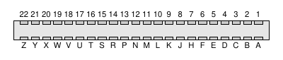
| Gnd | 1 | A | Gnd |
| 5V | 2 | B | /ROMH |
| 5V | 3 | C | /RESET |
| /IRQ | 4 | D | /NMI |
| R/W | 5 | E | φ2 |
| DotClk | 6 | F | A15 |
| /IO1 | 7 | H | A14 |
| /GAME | 8 | J | A13 |
| /EXROM | 9 | K | A12 |
| /IO2 | 10 | L | A11 |
| /ROML | 11 | M | A10 |
| BA | 12 | N | A9 |
| /DMA | 13 | P | A8 |
| D7 | 14 | R | A7 |
| D6 | 15 | S | A6 |
| D5 | 16 | T | A5 |
| D4 | 17 | U | A4 |
| D3 | 18 | V | A3 |
| D2 | 19 | W | A2 |
| D1 | 20 | X | A1 |
| D0 | 21 | Y | A0 |
| Gnd | 22 | Z | Gnd |
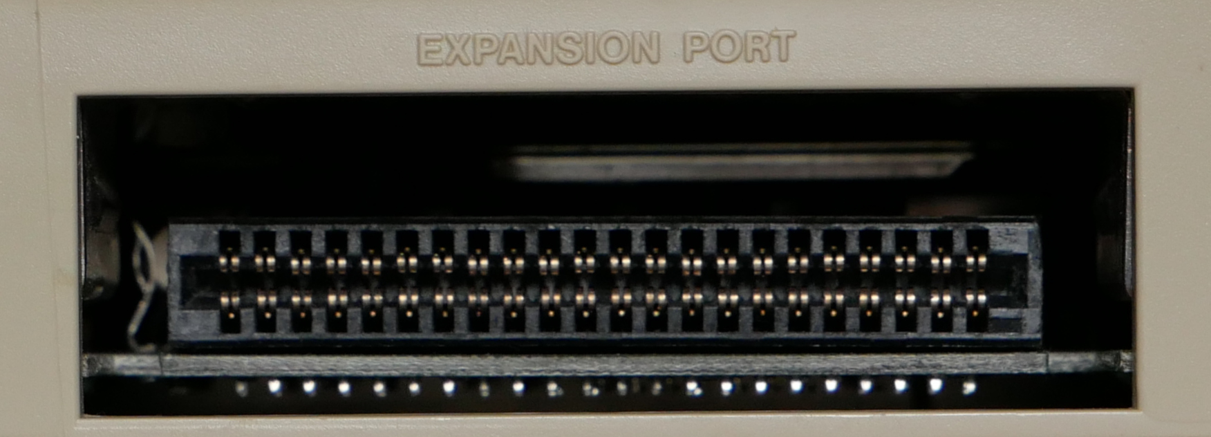
The expansion port
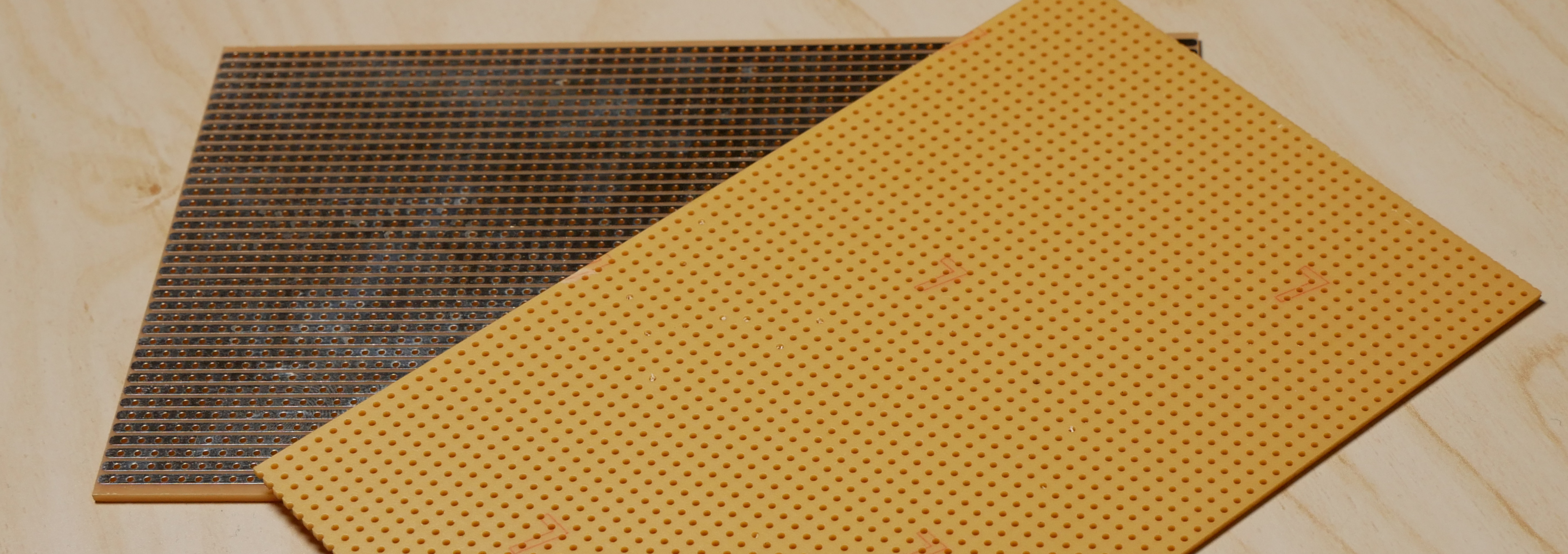
The main difficulty is related to the shape and pinout of the C64 expansion port connector. This is a dual-row edge connector, and although it uses the same 0.1" spacing as a stripboard, signals are supposed to be routed on both sides of the cartridge PCB:
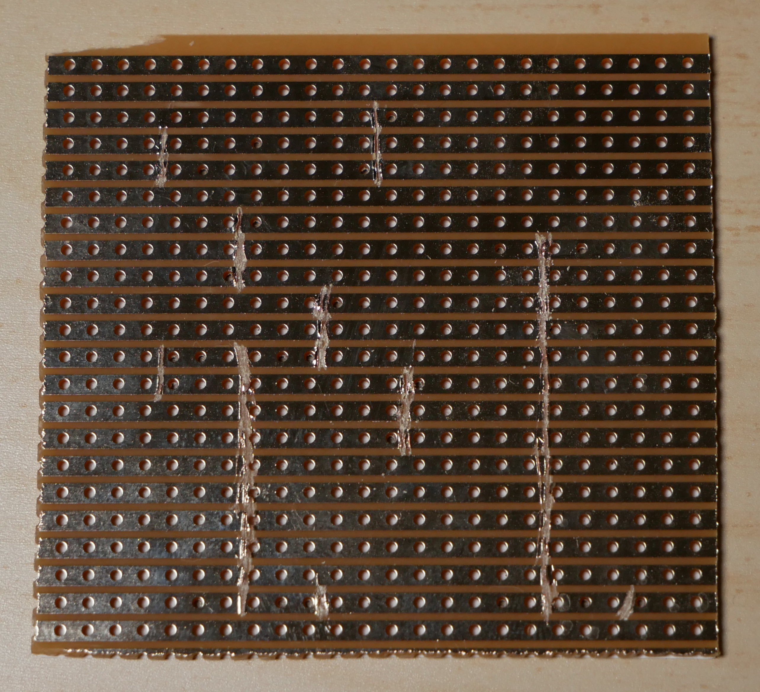
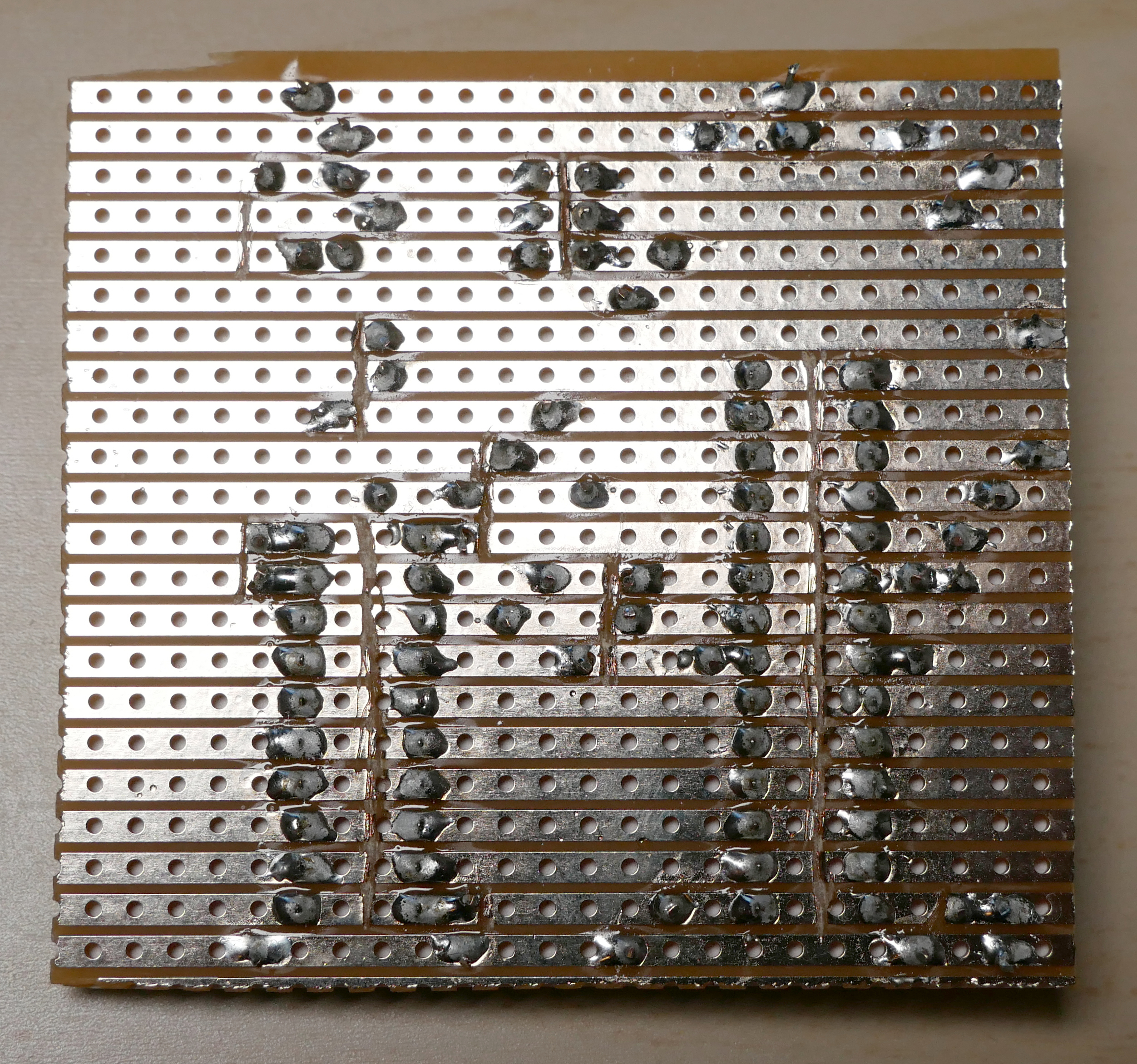
The stripboards (Veroboards) that I normally use when wiring up electronic projects by hand only have copper strips on one side:
But as always the C64 is eminently hackable. It turns out that all the signals we really need are on the same side of the connector, the top side. We have the power supply, the EXROM line that tells the computer that an 8 kB ROM cartridge is present, the ROML line that signals when the computer is trying to read from said 8 kB ROM, and the data bus (D0–D7) where the ROM will place its output. We don't have access to the CPU clock, but we do get the dot clock which is eight times faster. But hang on a second! Don't we need the address bus?
Principle of operation
Here's the idea: Every time the C64 tries to access the cartridge ROM, the chip-select line, ROML, goes low for one CPU half-cycle (four dot clocks). The next half-cycle is reserved for the video chip which will never try to access cartridge ROM. So there will be one high-to-low transition of ROML for every byte the C64 fetches from the cartridge. At boot time, the C64 Kernal looks for a five-byte magic string (“CBM80”) in the ROM area, to see if an autostarting cartridge is present. We know exactly in what order these five bytes are read, so we can simply provide them one at a time whenever ROML goes low. If the five bytes match, the Kernal jumps through a vector in the ROM area, and again we can provide these bytes right when they are expected. Then we can proceed with opcodes and operands in a completely deterministic sequence.
There are two caveats: First, we can't see the C64 reset line, so the autostart hack will only work immediately after power-on. Secondly, if the CPU is reading from cartridge ROM when the video chip stalls the CPU (on a so called badline), the CPU will keep reading the same address three times in a row. This will mess up the sequence. Therefore, as early as possible after power-on, we'll send opcodes to turn off the display and disable all badlines.
Schematic
In practice, there are many ways to implement this idea. The most important thing to get right is to stay off the data bus when ROML is high. I chose to do this with a dedicated 8-bit tristate buffer, 74541 (datasheet), with its output-enable signal directly connected to ROML. Then I use an AVR microcontroller to clock out new data on every rising edge of ROML.
Here's the schematic:
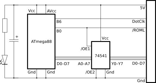
And here's the complete list of components:
Stripboard (cut to size)
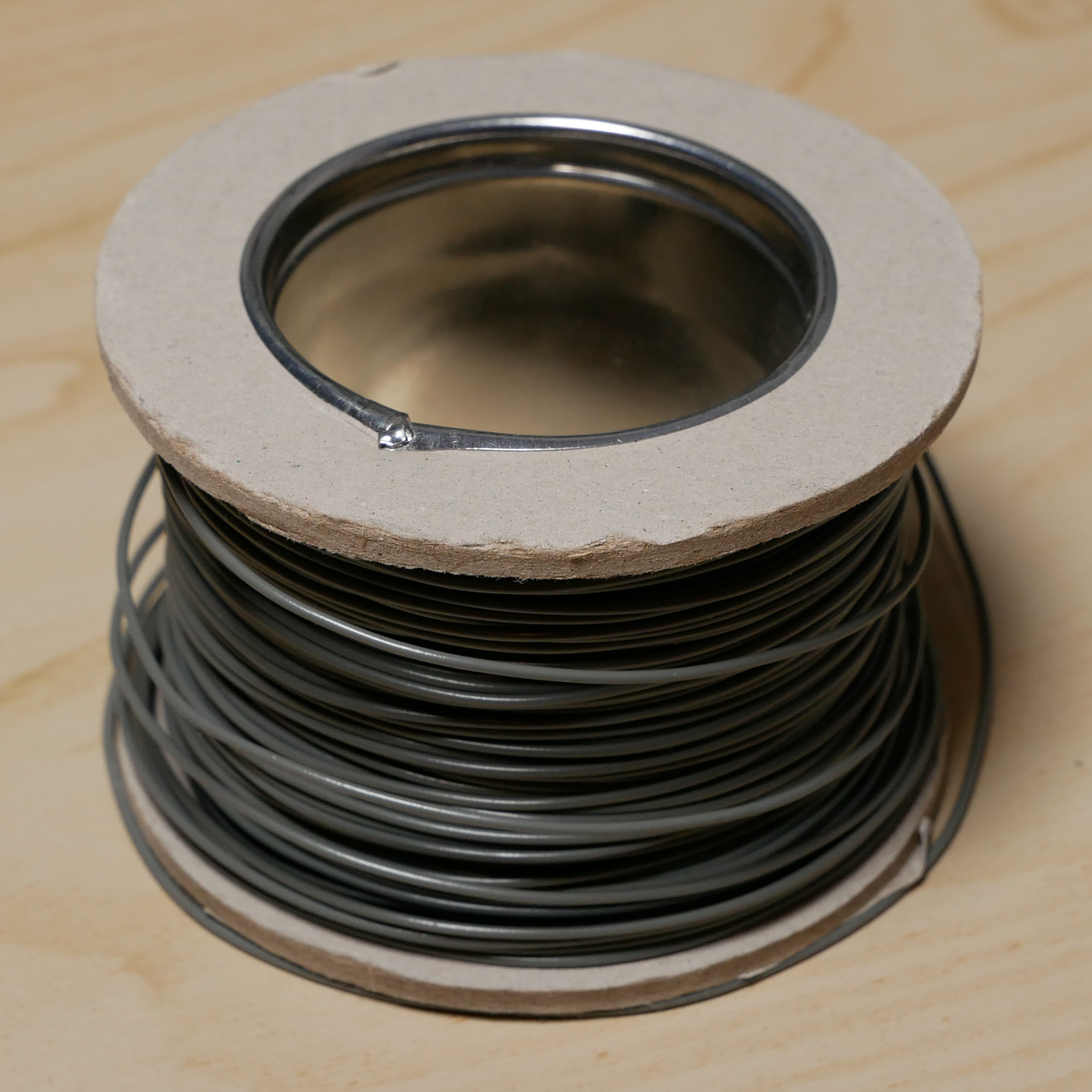
Wire
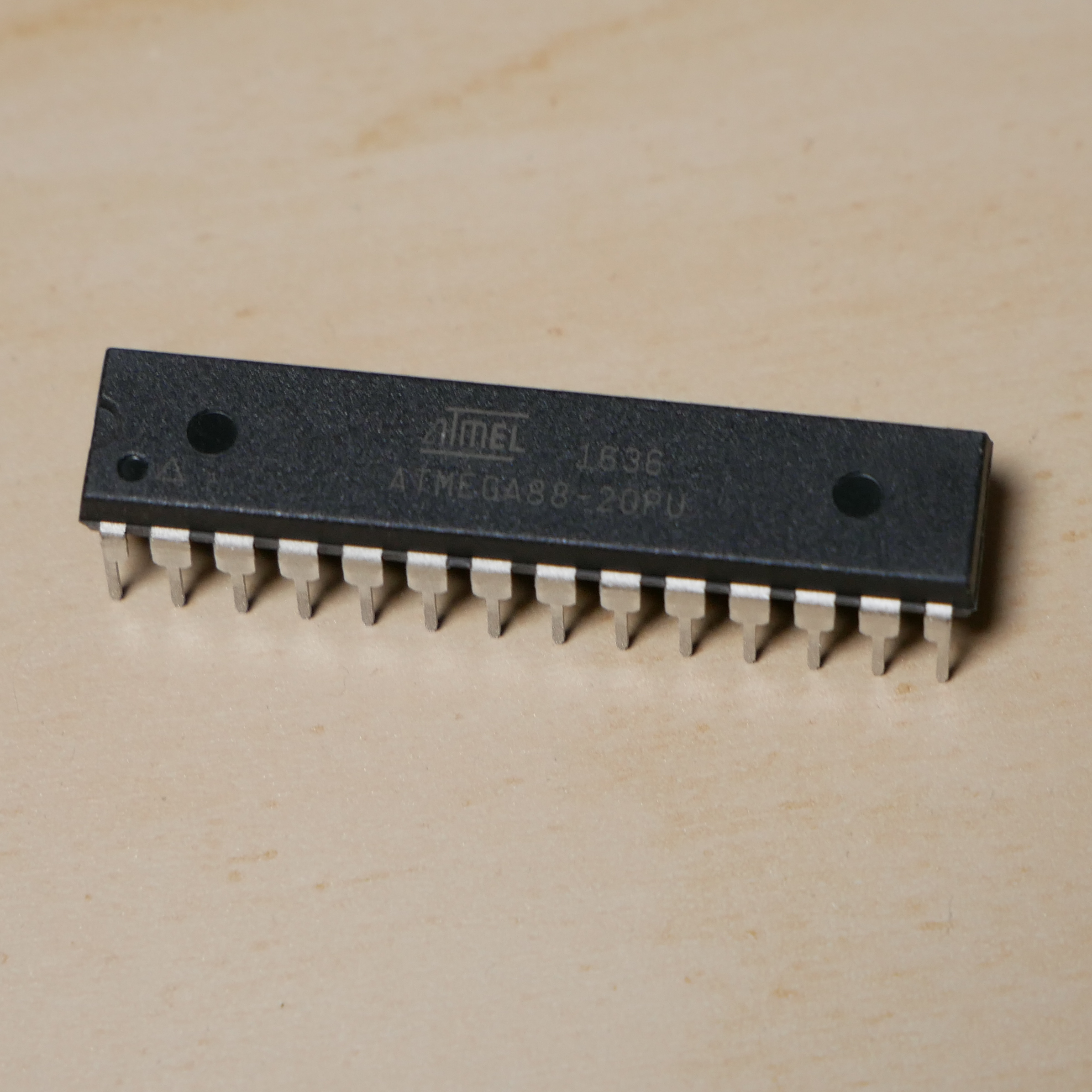
Microcontroller (ATmega88)
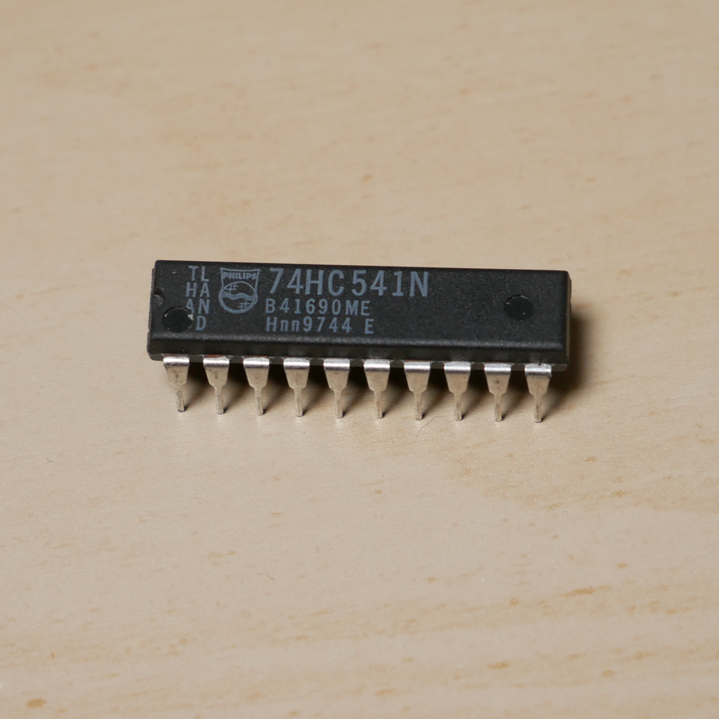
Tristate buffer (74541)
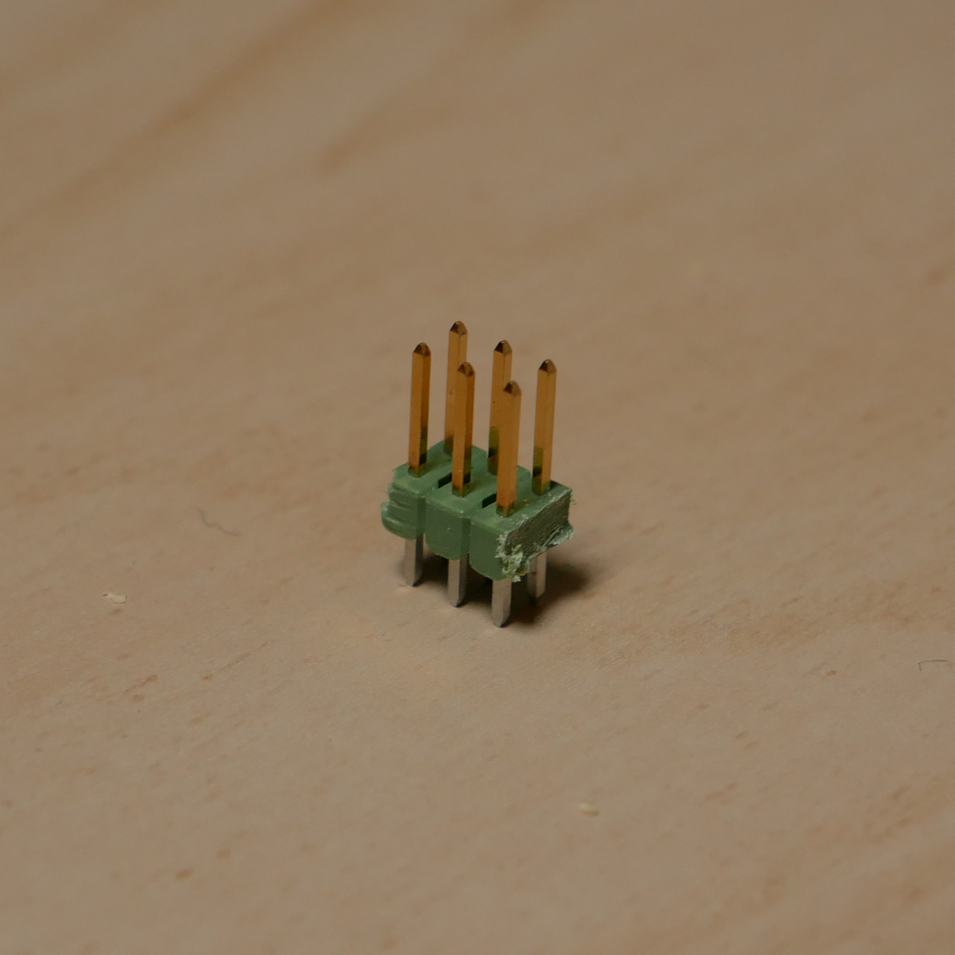
Header (for programming the ATmega88 while mounted)
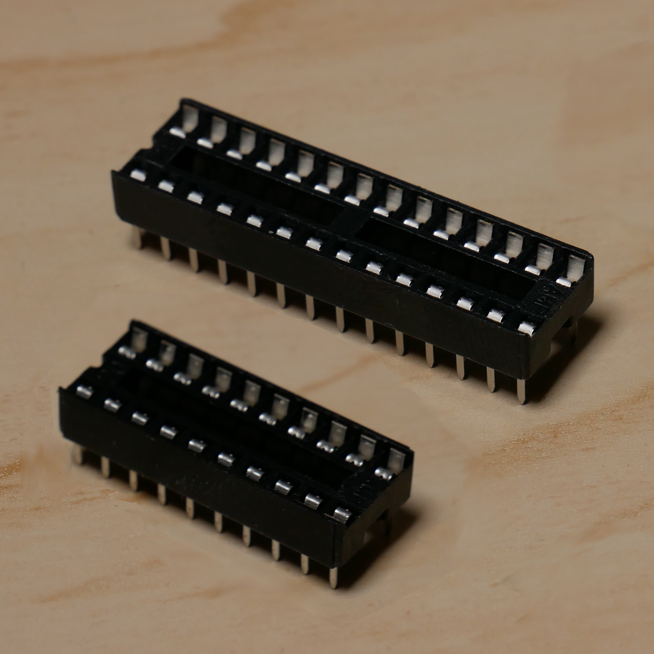
Chip sockets (28p and 10p, optional)

Capacitor (optional, for power stability)
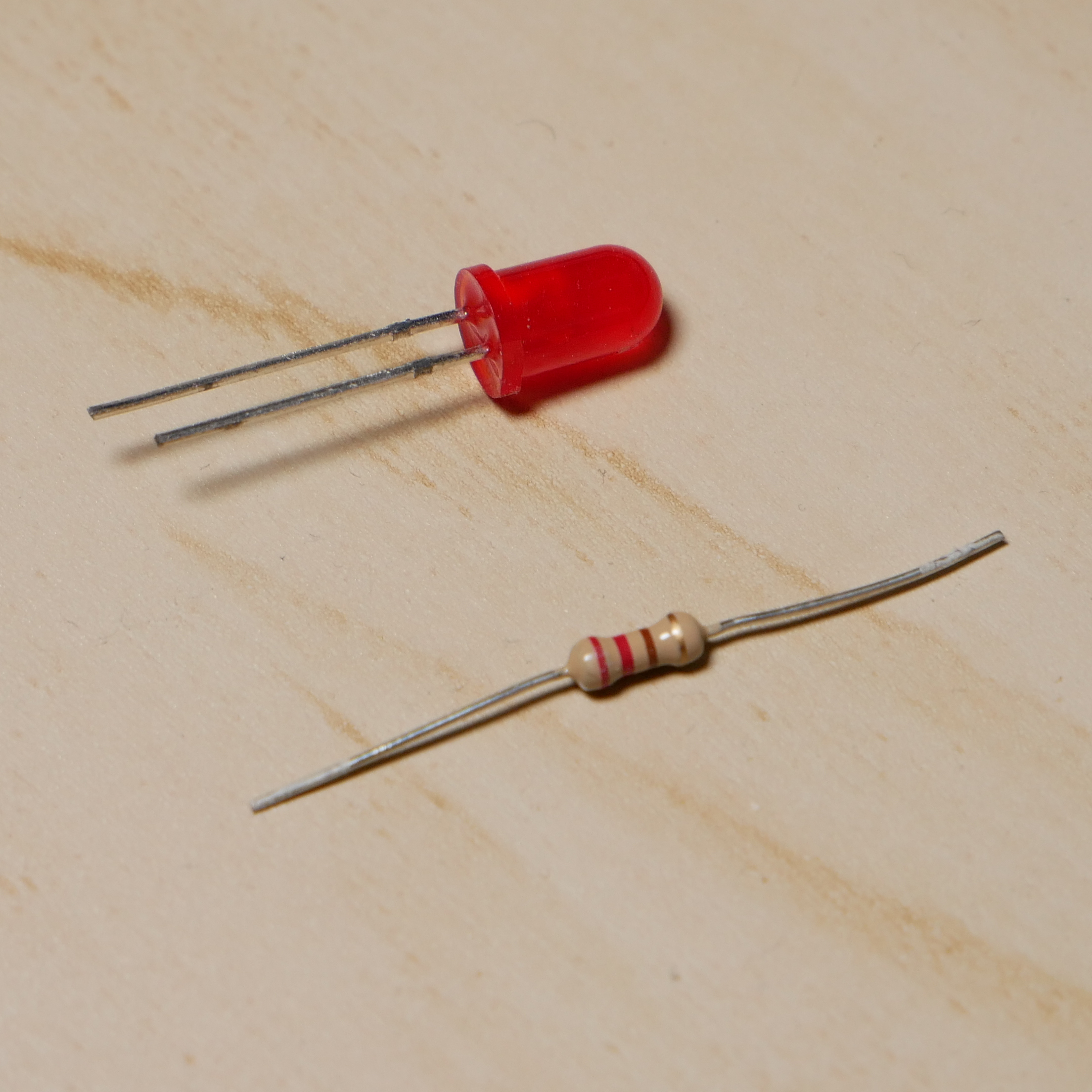
LED and resistor (optional, for troubleshooting)
Firmware
Again, there are many ways to implement this single-sided cart idea in hardware, but I went for an old favourite of mine, the ATmega88 microcontroller. It can be clocked by an external signal (i.e. the 8 MHz dot clock) and can house up to 8 kB of firmware, which is reasonable for a simple C64 application.
For speed and minimal overhead, the entire firmware will be implemented in AVR assembler. The workhorse is the following loop:
loop:
        sbic    PINB, 0         ; 1 or 2 cycles
        rjmp    loop            ; 2

        lpm     r16, Z+         ; 3
        out     PORTD, r16      ; 1
        rjmp    loop            ; 2
It starts with a tight sbic/rjmp loop that waits for ROML to be low (Skip next instruction if Bit in I/o-register is Clear, followed by a Relative JuMP). This will poll ROML every three cycles, and because ROML is low for four cycles we're guaranteed to catch the event. Next, we read from flash (lpm, Load from Program Memory) into register r16 and increment the Z pointer (Z on the AVR refers to the pair of registers r31:r30). Then we output register r16 to Port D and go back to the beginning of the loop.
When the C64 is executing code from cartridge ROM, it will request a new byte on every CPU cycle, i.e. every eight dot clocks. The loop above completes in exactly eight AVR cycles if the sbic instruction skips the rjmp every time. That means we are able to keep up! Furthermore, after detecting a low level on ROML, five more AVR cycles will pass until the new value is emitted. This will guarantee that the previous value remains on the bus until ROML has returned to a high state.
When ROM accesses are more sparse, the sbic/rjmp loop will delay accordingly. Note that there is no need to wait for ROML to return to a high state, because we know that it happens four dot clocks after the high-to-low transition.
Bootloader
So we first transmit the magic “CBM80” string—backwards, because that's how the comparison is carried out by the Kernal—and then an arbitrary address in the ROM address space. Then we can begin to transmit opcodes and operands. We can make the C64 write arbitrary bytes to memory with a pair of instructions (lda #value : sta address). But for every byte written in this way, we'll be consuming five bytes of data from the table in AVR flash. Since we only have 8 kB of flash in total, it would be wasteful to deliver the entire C64 application like this. Instead, we should as quickly as possible install a piece of code in C64 RAM and do the rest of the loading from there. This will be our Stage 2 Bootloader (Stage 1 is the streamed opcodes). Let's put the following routine in RAM at address $6000:
6000    ad 00 9d    lda     $9d00      ; read from ROM
6003    9d 00 60    sta     $6000,x    ; store into RAM
6006    e8          inx                ; increment
6007    d0 f7       bne     $6000      ; and loop until zero

6009    ee 05 60    inc     $6005      ; increment high byte
600c    10 f2       bpl     $6000      ; and loop until we reach $8000

600e    ...application...
When fetching a byte from the cartridge, we can read from any address in the cartridge ROM range ($8000–$9fff). The reason for picking $9d00 is because the byte $9d appears later as an opcode. This saves two bytes in Stage 1. Here's the complete AVR code:
        .global __vectors

PINB    = 0x03
DDRD    = 0x0a
PORTD   = 0x0b

__vectors:
        rjmp    main                    ; AVR reset vector
main:
        ldi     r16, 0xff
        out     DDRD, r16               ; set data direction to output

        ldi     r16, 0x30               ; first byte, '0'
        out     PORTD, r16

        ldi     r30, lo8(table)
        ldi     r31, hi8(table)

loop:   sbic    PINB, 0
        rjmp    loop

        lpm     r16, Z+
        out     PORTD, r16
        rjmp    loop

table:
        .byte   0x38,0xcd,0xc2,0xc3     ; CBM8 backwards
        .byte   0x00,0x80               ; boot vector

        ; stage 1

        .byte   0xa9,0x03               ; lda #$03
        .byte   0x8d,0x11,0xd0          ; sta $d011 (disable badlines)

        .byte   0xa9,0xad               ; lda #$ad
        .byte   0x8d,0x00,0x60          ; sta $6000
        .byte   0xa9,0x00               ; lda #$00
        .byte   0x8d,0x01,0x60          ; sta $6001
        .byte   0x8d,0x04,0x60          ; sta $6004
        .byte   0xa9,0x9d               ; lda #$9d
        .byte   0x8d,0x02,0x60          ; sta $6002
        .byte   0x8d,0x03,0x60          ; sta $6003
        .byte   0xa9,0x60               ; lda #$60
        .byte   0x8d,0x05,0x60          ; sta $6005
        .byte   0xa9,0xe8               ; lda #$e8
        .byte   0x8d,0x06,0x60          ; sta $6006
        .byte   0xa9,0xd0               ; lda #$d0
        .byte   0x8d,0x07,0x60          ; sta $6007
        .byte   0xa9,0xf7               ; lda #$f7
        .byte   0x8d,0x08,0x60          ; sta $6008

        .byte   0xa2,0x09               ; ldx #$09
        .byte   0x4c,0x00,0x60          ; jmp $6000

        ; stage 2

        .byte   0xee,0x05,0x60          ; inc $6005
        .byte   0x10,0xf2               ; bpl -14

        ; application follows
Note that we don't need to install the full Stage 2 routine before starting to execute it; the first nine bytes are enough. Then we initialize X to nine and jump to the newly installed code, where we will pull in the remaining five bytes of Stage 2 code followed by the application. When 8 kB have been transmitted, the outer bpl-loop falls through to the application itself, which should be linked to execute from address $600e.
Step-by-step instructions
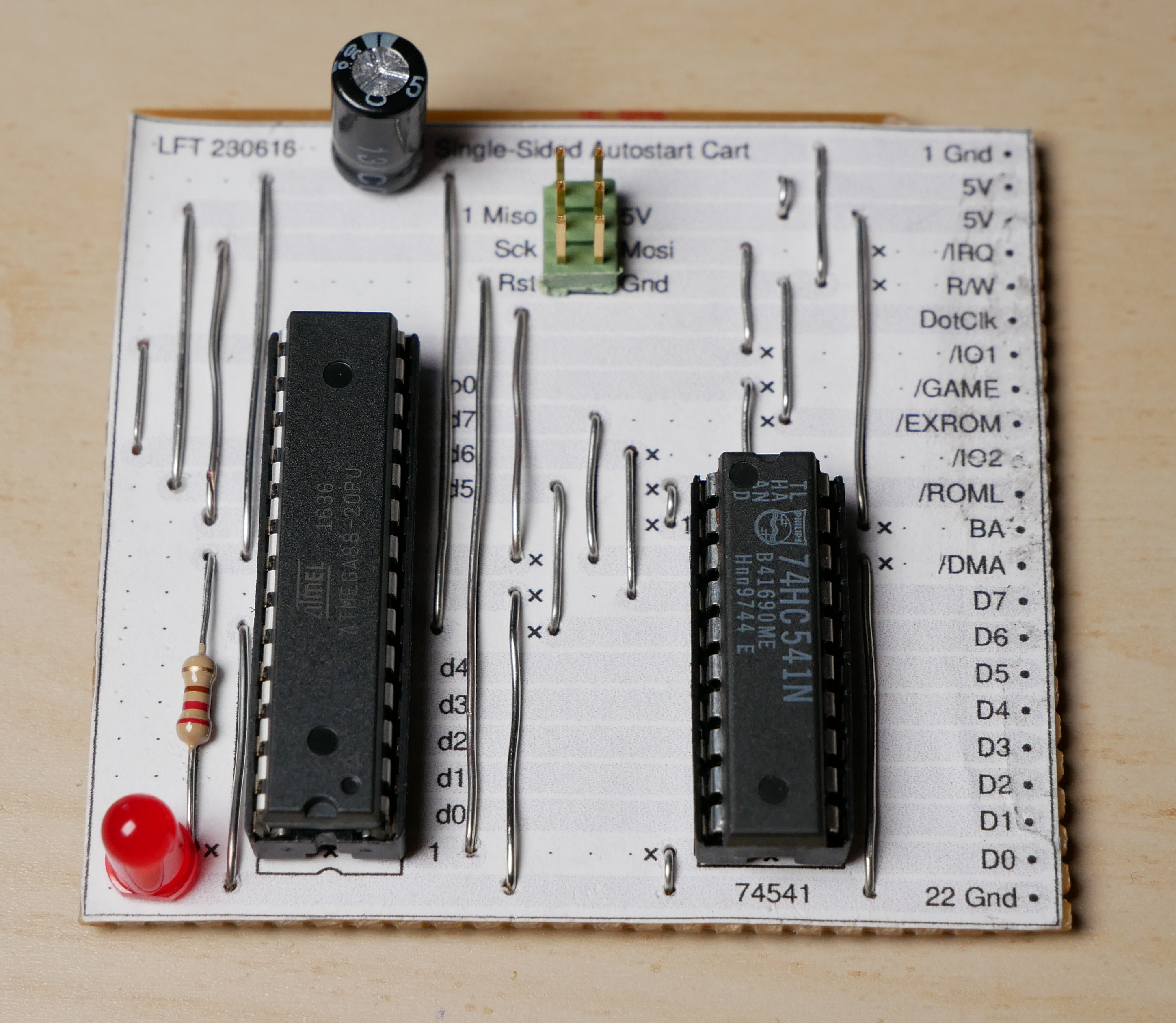
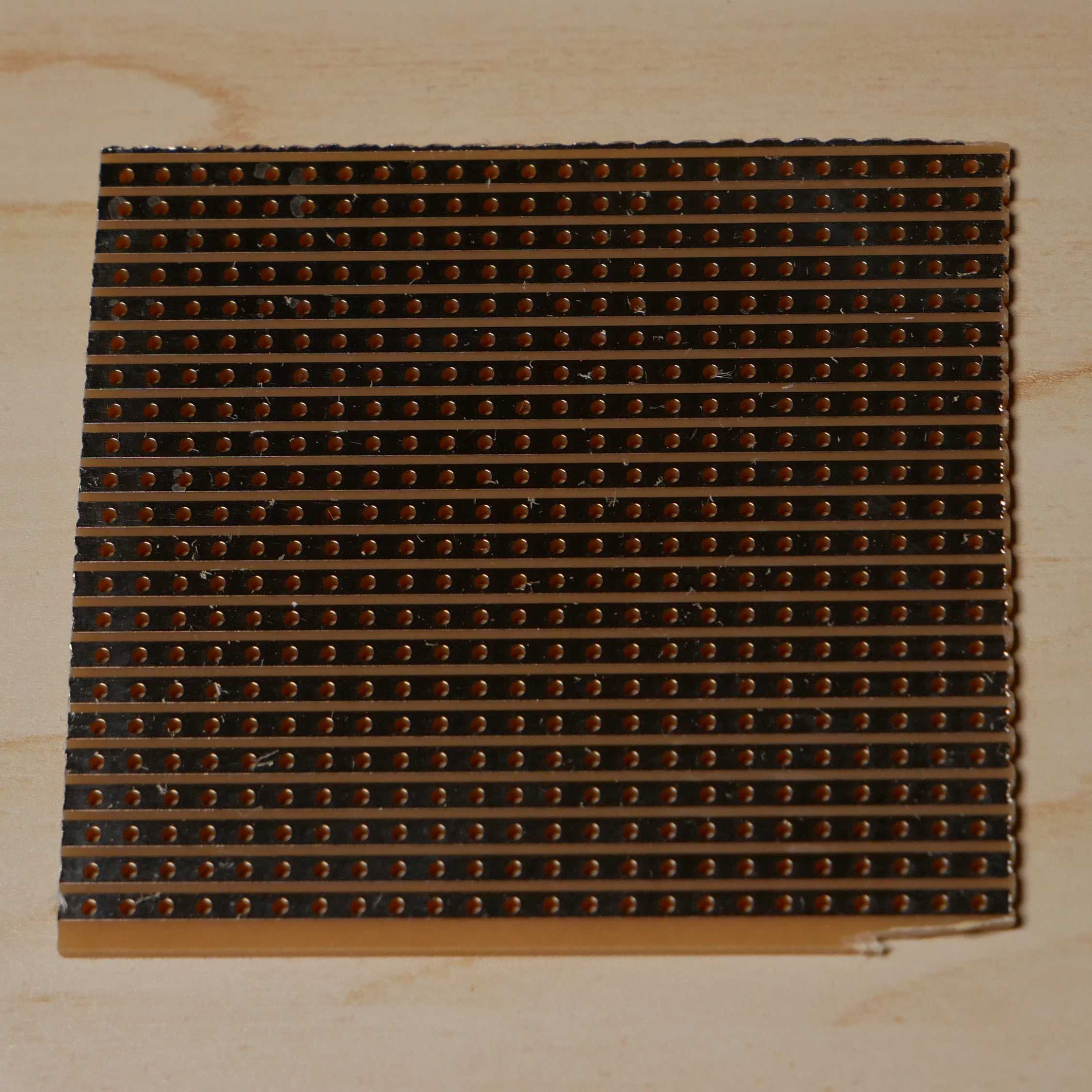
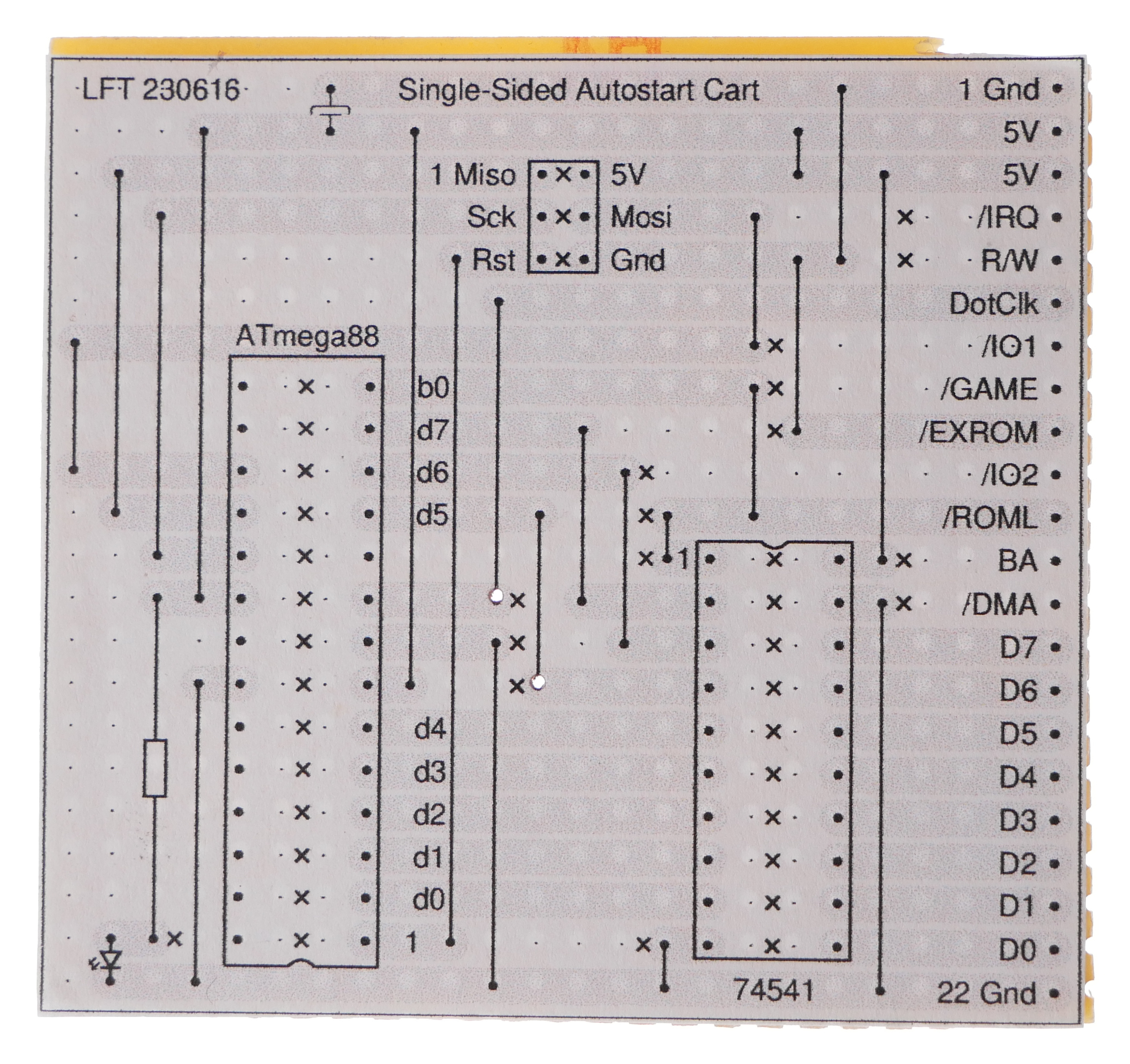
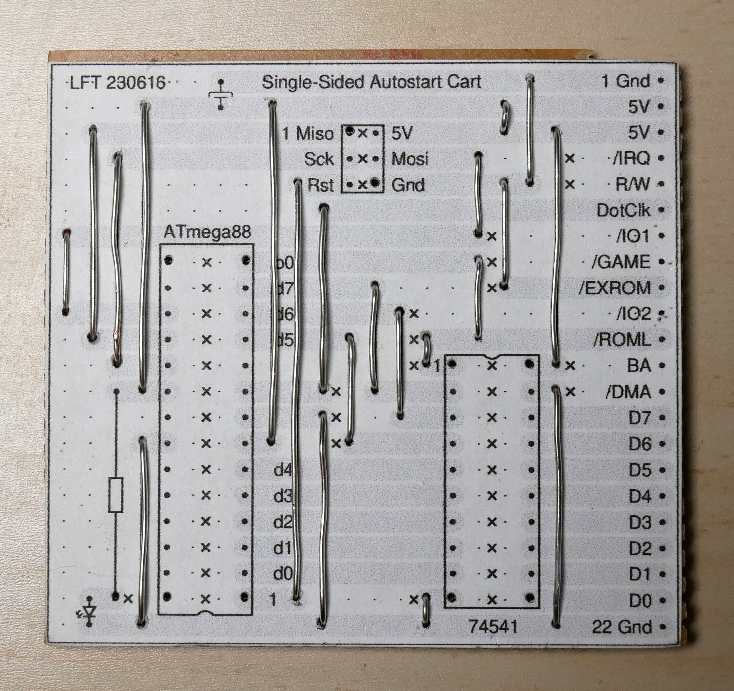
When I work with stripboards, I use a set of PostScript macros to draw a physical layout of the schematic.
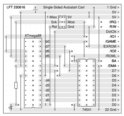
(click for PDF version)
Start by cutting out a piece of stripboard, 22 strips, each 24 holes long. Leave a millimeter or so around the edges. This may involve sawing through a strip along its length. If you use a power saw or sander, wear a face mask because dust from the stripboard is very bad for your lungs.
Check that the board fits inside the expansion slot of your C64; you may have to file down the edges a bit. The copper strips should be facing upwards. Check that the strips are aligned with the tongues of the connector.
Print the physical layout on ordinary paper, cut it out, and glue it to the stripboard. Remember to print without any scaling (evince has options for that under “Page Handling”). Use a regular glue stick and hold the board up to the light to check that the dots line up with the holes behind the paper.
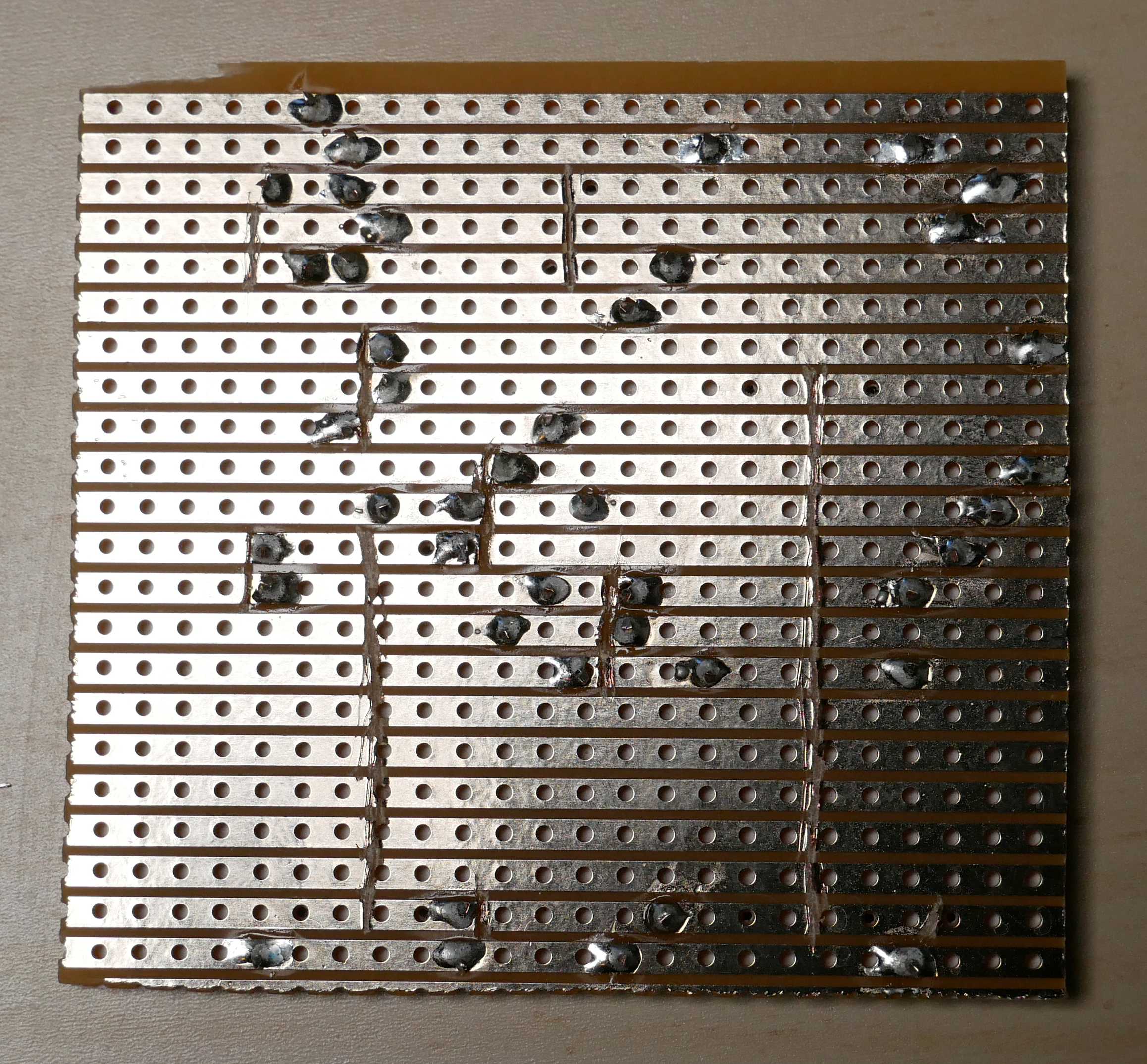
Next, cut the strips at the “x” marks e.g. with a tile scribe. This design has 42 cuts in total. To locate the correct spot for a line of cuts, poke holes (the tile scribe is handy for this too) through some of the dots nearby. You can see the holes in the paper from the backside, especially if you light the board from behind.
When you're done, check every cut with a continuity meter; sometimes there's a tiny bridge of metal left.
Solder all the wires in place. For the shortest wires, you can reuse component leads from earlier projects. Don't overtighten the wires; when they cool down, they shrink a little and may bend the board.
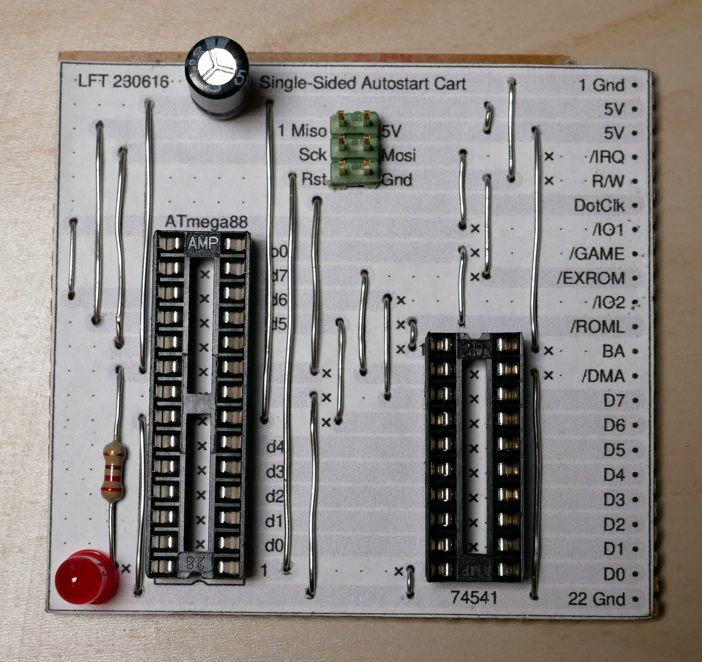
Solder the remaining components and sockets. I like to go in order of increasing height.
Double-check the orientation of the two chips (“1” marks the location of pin 1), the LED, and the capacitor. Electrolytic capacitors can explode if installed backwards, so make sure the shorter negative lead is connected to Gnd.
Insert the chips into their sockets. As a final test, check that there isn't a short between Vcc and ground.
Obviously, if you build this and connect it to a C64, you're doing so at your own risk. But the expansion port is no more sensitive that the game ports or the user port.
Fuse bits
In addition to programming the firmware into the AVR chip, you have to configure the clock source (external clock) and select an appropriate reset delay. This is done using the so called fuse bits of the AVR.
A reset delay is necessary because there will be some noise on the ROML signal while the C64 is powering up. A proper cartridge would react to the reset signal from the C64, but as discussed that signal is on the wrong side of the connector so we can't see it. I've measured with a logic analyzer, and 65 ms is more than enough for ROML and the clock to stabilize, and the C64 reset signal doesn't rise until half a second after power-on.
To select an external clock and a 65 ms reset delay, write 0xe0 into the low fuse byte of the ATmega88.
The procedure for updating the fuse bits depends on what AVR programmer you're using. With avrdude, for instance, you can start the program with the -t option and then type:
write lfuse 0 0xe0
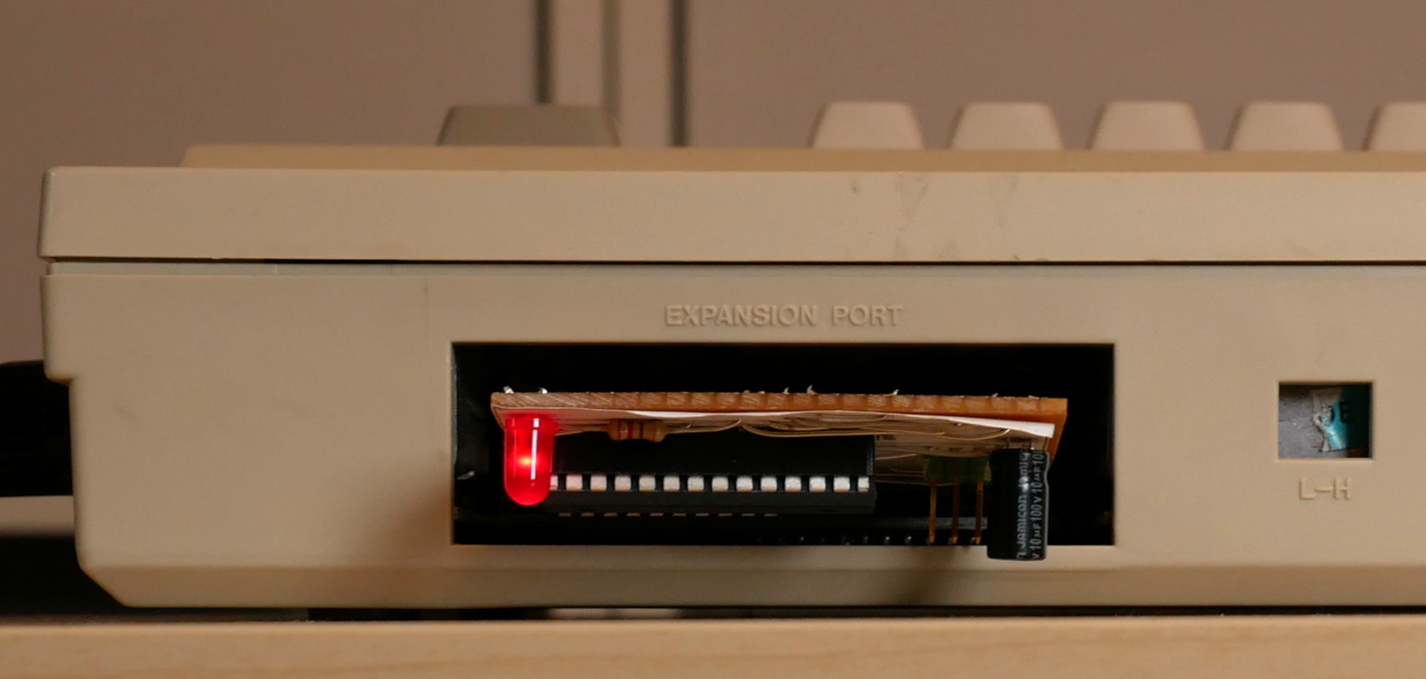
In action
I'm using this cartridge in my latest C64-based musical instrument.
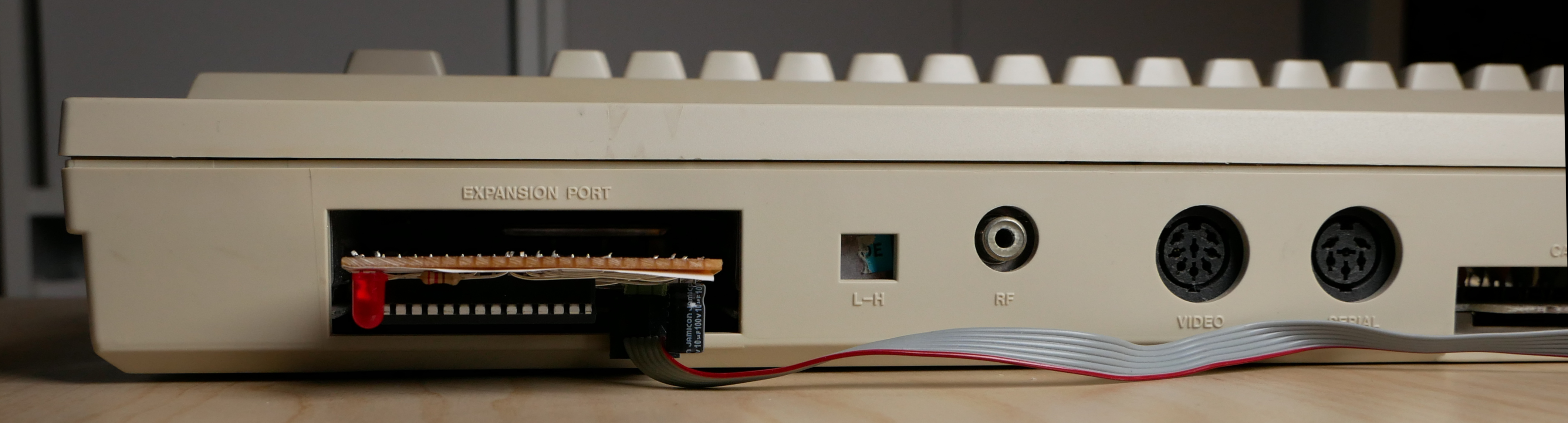
Cartridge in expansion slot with AVR programming cable attached.
Further ideas
Several other signals are available on the top row of the connector. Once the boot procedure has completed, this cartridge just sits there, stuck in the transfer loop and waiting for a ROML that never comes. To get out of the loop, one could tie IO1 or IO2 to a pin on the AVR and enable the corresponding pin-change interrupt. In this way, the C64 application could access the corresponding I/O area once to put the AVR in a completely new mode.
Furthermore, the C64 data bus could be directly connected (circumventing the buffer chip) to a different port on the AVR, configured as input. Or one could replace the buffer chip with a bidirectional gate. Either approach would allow two-way communication where the C64 could send a byte to the AVR by writing to the I/O area and then receive a byte by reading from the ROM area. Since we're no longer executing code directly from ROM, the timing requirements would be more relaxed on the AVR side in this mode.
Once a communication protocol is in place, the AVR firmware could be extended to handle various requests like performing fast multiplications, measuring analogue voltages, or reading and writing the built-in EEPROM.
All from a single-sided stripboard in the cartridge port.
Posted Friday 30-Jun-2023 12:44
Discuss this page
Disclaimer: I am not responsible for what people (other than myself) write in the forums. Please report any abuse, such as insults, slander, spam and illegal material, and I will take appropriate actions. Don't feed the trolls.
Jag tar inget ansvar för det som skrivs i forumet, förutom mina egna inlägg. Vänligen rapportera alla inlägg som bryter mot reglerna, så ska jag se vad jag kan göra. Som regelbrott räknas till exempel förolämpningar, förtal, spam och olagligt material. Mata inte trålarna.
Christopher Phillips
Fri 30-Jun-2023 13:53
Nice work once again, LFT.
6 more comments hidden. Click to show all.
Linus Åkesson
Fri 7-Jul-2023 11:19
The reason for putting Stage 2 immediately before the application is to avoid the need for a JMP. But you have a point; it's possible that switching to zero-page instructions would save enough bytes to compensate for this. To be investigated.
That's only because the byte $09 didn't appear in the Stage 2 code. Otherwise I would have done it.
Linus Åkesson
Fri 7-Jul-2023 11:26
The loop on the AVR already needs eight cycles per iteration, so in order to add more complexity one would have to unroll the loop: Send $a9, send a byte from the table, send $8d, send the address LSB, send the address MSB, increment the address, and loop back to the beginning. The unrolled AVR code would also consume a lot of flash space, probably more than the table of opcodes and operands.
Homay Danesh
Fri 28-Jul-2023 13:34
I am beginner
The hardware discussion was wery simple and I have made it.
How can apply the software on avr and how can transfer programs to C64?
Step wise
Wed 9-Aug-2023 15:09
The byte needn't be $09. You can load $00 to X, and compensate by either changing the memory address where you load, or just decrease the base address in the X-indexed STA statement in Stage 2. As far as I understand, the X-indexed STA handles the carry in the effective address correctly and without a timing penalty.