


C64 Theremin
The Theremin is one of the earliest electronic instruments. It's played by moving one's hands in front of two antennas: One controls pitch and the other controls volume.
Electronically, the instrument works by monitoring the capacitance between its antennas and Earth and detecting the small increase that occurs when a human moves closer. The amount of extra capacitance is inversely proportional to the distance.
I used a C64, two 555s, four resistors, a spoon, and a clamp to build a working Theremin. In the video I try to explain how it works in layman's terms. What follows below is a more thorough description for those who want to dig deeper.
I, capacitor plate
The human body is, somewhat simplified, a volume of salt water surrounded by a thin layer of skin. Salt water conducts electricity. Large parts of the Earth also conduct electricity—the groundwater, certainly, but also the damp soil above it. Even if you're standing in a dry place wearing rubber shoes, you're still close enough to this huge subterranean conductor to be capacitively coupled to it.
This means that ions (molecules with a charge) inside your body and inside the Earth can move around to create, for a short time, the illusion of an electric current flowing across the gap between you. In reality, negative charges are piling up on one side of the gap, and positive charges on the other, holding each other in place with the electromagnetic force. When there's no more room for charged particles—when the system has reached its capacitance—the current stops flowing. The capacitance between a human and the Earth is typically of the order of 100 pF (pico-Farads, sometimes pronounced “piff”) and decreases with distance.
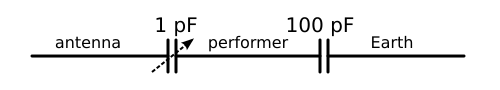
A slab of metal such as a Theremin antenna also conducts electricity, and interacts with the human body in a similar way. Electrons pile up in the antenna while positive ions pile up inside the closest body part, or the other way around depending on which way the current flows across the gap. This capacitance is much smaller, of the order of a single pF, and likewise decreases with distance.
When you connect two capacitances—let's call them A and B—in series, the total capacitance is (A⁻¹ + B⁻¹)⁻¹. This will always be less than each of the capacitances involved. Furthermore, if one of them (B, say) is much larger than the other, then its inverse (B⁻¹) becomes so small that it can be ignored. Therefore, the whole system of antenna, human, and Earth has a capacitance of the order of a single pF that decreases with the distance between the antenna and the human.
Schematically,
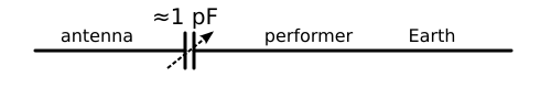
behaves in practice like:
Ah, interjects the astute reader, but if the human body forms a capacitor with the Earth simply because it is a conductor, then surely the Theremin antenna also forms a capacitor with the Earth for the same reason. And indeed, the capacitance between one of my makeshift antennas and the Earth turns out to be about 30 pF. So what we actually have is this:
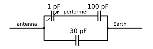
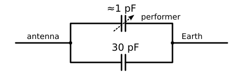
Or, in practice:
This new capacitance shunts (is connected in parallel with) the one we were discussing previously, and parallel capacitances add together. So when we measure the total capacitance between antenna and Earth, we can expect to see something of the order of 30 pF, with a 3% variation (an extra pF or so) depending on the distance between antenna and performer.
Earth, ground, and capacitive touch displays
When recording audio, I always ground my C64 in order to reduce mains hum. But strictly speaking, the ground cable to Earth isn't necessary for a Theremin to work.
As long as the circuit is powered from mains, it will be capacitively coupled to mains ground, and thus to Earth. In a switched-mode power supply, there's typically a pair of capacitors connecting ground (on the secondary side) to each of the AC inputs (on the primary side) as a measure against electromagnetic interference. We really only need a capacitor to ground on the primary side, but the mains plug is symmetrical, so there's no way to know which input is live and which is connected to ground, and that's why there are capacitors to both inputs. I suppose it's no big mystery where the mains hum is coming from.
These so called Class Y capacitors are designed to fail—if or when that happens—by breaking the connection rather than shorting it; I'll leave it as an exercise to figure out why that is important.
Schematically, an ungrounded version of the circuit would look like this:
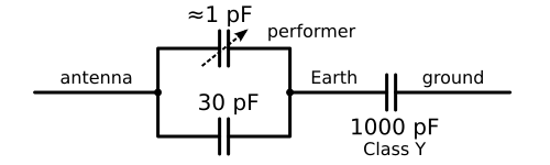
If the Class Y capacitor is large enough (and they are usually at least 1000 pF), then, being connected in series with the others, it will have a negligible effect on the measured capacitance. So the circuit still works!
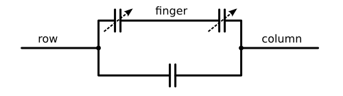
Will it operate from a battery, though? Handheld devices with touch-sensitive displays are all the rage these days (I'm told), and these displays use capacitance to detect that a human is nearby, much like a Theremin. But instead of relying on a connection to Earth, they measure the capacitance between two antennas—or strips of transparent conductive film, as it were—right next to each other. The human finger forms a capacitor with each of these strips, increasing the number of charged particles that can crowd together inside them. The strips are arranged in rows and columns that cover the entire surface of the screen. So a fingertip increases the mutual capacitance between the nearest row and column, and by carrying out multiple measurements it becomes possible to pinpoint the location of the finger.
What about a battery-operated Theremin, then? Suppose its circuit ground is connected to a large metallic object, perhaps the ground plane of a PCB, the enclosure, the stand, or some other kind of metal shield. One could think of this as a way to capacitively couple the circuit to Earth. But it's also illuminating to think of this metallic object as a secondary sensor, a common “row” strip to the two “column” antennas. As the hand moves towards an antenna, it is also in the vicinity of the common “row” conductor, the signal ground.
These two ways of reasoning about the circuit both suggest that a battery-operated Theremin could work. But the instrument would be sensitive to a human hand moving towards the antenna as well as towards the ground conductor. I haven't tried, but I think it would be harder for a performer to control it, compared to an ordinary mains-powered Theremin.
How to measure capacitance
Our circuit needs to measure the capacitance between two points. Here's a common way to do it: Connect a voltage source (let's say 5 V) between the antenna and ground and give everything a bit of time to settle. Then, disconnect the voltage source and allow the stored charge to flow back out of the antenna, through a resistor to ground. See how long it takes until the current stops flowing—i.e. until the voltage across the resistor drops below some threshold (let's say 1 V). This time is proportional to the capacitance.
A typical music driver on the Commodore 64 will update the SID chip registers once per video frame, so a reasonable goal is to be able to complete a full measurement procedure as often as that. On a PAL system, a video frame lasts for 20 ms. Thus we'd like to discharge 30 pF over the course of, say, 15 ms (leaving some margin), with an expected variance of 3% of 15 ms = 450 µs. On a 1 MHz machine, that corresponds to a window of 450 clock cycles during which, at some point, the voltage drops below the threshold value. So if we could determine exactly on what clock cycle this happens, we'd get about 8–9 bits of precision to represent the full pitch range, which seems workable.
Unfortunately this approach doesn't work in practice. To begin with, the 6510 CPU in the C64 can't read from input ports on every cycle, even if we distribute the two measurement procedures (volume and pitch) across the video frame so we only have to deal with them one at a time. Using a big unrolled loop, we can monitor a single input every sixth cycle. If we get really clever and execute code inside the I/O registers, we might get it down to once every three cycles. The lightpen input comes to mind: Its X coordinate is reported with a two-cycle resolution, but this would only work for one of the antennas, since there's only one lightpen input. There's also a special mode in the CIA chips where they increment Timer B with every Timer A overflow if the CNT input is high; that would allow us to monitor the CNT signal with a two-cycle resolution, since that's the maximum Timer A overflow rate. With this method, we could achieve 7–8 bits of precision at best.
But there's a more fundamental problem: In order to discharge 30 pF in 15 ms, we'd have to discharge through a 500 MΩ resistor, which is huge. Large-valued resistors tend to be noisy: The resistance will vary with temperature and humidity, and even a small induced current from the environment will result in a large voltage change on the output. So it would be preferable to discharge through a smaller resistor. But this would make the whole process a lot faster, and the window of time in which we could observe the transition would shrink to a few clock cycles or even less. We'd lose all of the precision.
Another issue is that there's no reliable way, on a C64, to detect exactly when an incoming voltage drops below a threshold value. You'd think that a digital input does exactly that: When the voltage drops below a certain level, it is interpreted as a logic zero instead of a logic one. But the boundary between zero and one is really a range of voltages, and the actual tipping point varies over time in unpredictable ways. So we would have to use an external component, an analogue comparator, to monitor the voltage and produce a clean digital signal when the threshold is reached.
What about the paddle inputs? They are analogue, and actually designed to measure capacitor discharge times. But alas, they are internally connected to 1000 pF capacitors to ground. Our little 1 pF variation would disappear completely. Again, we could use an external component such as an opamp to force the paddle input to follow our weak antenna signal.
But if we're going to use an external chip anyway, we might as well solve all of the aforementioned problems in one go. We'll take a cue from the original Theremin design and use an oscillator to convert the capacitance into a frequency. For this, we'll use a chip that's almost as old as the integrated circuit itself: The 555 precision timer from 1972.
Well, that's not entirely true: I'm using a modern 555 replacement chip (built with CMOS technology), because it has lower stray capacitances and leakage currents and interferes noticeably less with our signal. But functionally it behaves in the same way.
The 555 contains two analogue comparators, a flip-flop, and a discharge transistor. Together with a capacitor and two resistors, those are all the building blocks you need to make a circuit that oscillates in a very robust and precise way. The comparators have fixed thresholds at 1/3 and 2/3 of the supply voltage. If you hook up the pins of the 555 in the right way (see below), it will charge your capacitor up to 2/3 of the supply voltage, then discharge it down to 1/3, then charge it up to 2/3 again, and so on, and you'll have a digital signal (on Pin 3, the output from the flip-flop) indicating whether it's currently charging or discharging.
The frequency of this digital signal is inversely proportional to the capacitance. As the capacitance goes up, the charging and discharging takes longer, and so the frequency decreases—and vice versa. The actual formula for the frequency in Hz is 0.48 / (RC).
Could we connect the output signal to a speaker and already have a working Theremin (albeit with a fixed volume)? No, not quite. Suppose we pick a resistor value that ensures that the output frequency is in the audible range. If we move our hand towards the antenna, the capacitance will increase, and the pitch will go down. That's backwards—on a real Theremin the pitch rises as you approach the antenna—but the main issue is that, as you might remember, the capacitance will only change by about 3%. A 3% change in pitch is less than a semitone, whereas a musically useful Theremin would need a range of about two octaves or more. And that corresponds to a four-fold increase in frequency, a 400% change.
The original Theremin solves this problem quite elegantly by having a fixed-frequency oscillator, tuned to match the frequency of the variable oscillator when the hand is far away from the antenna. The sinewave outputs from the two oscillators are then multiplied using a vacuum tube. This technique called heterodyning is common in radio engineering, and it produces a new signal with a frequency that is the difference between the frequencies of the two oscillators. That is, 0 Hz when the hand is far away from the antenna, and then gradually increasing as the hand gets closer. The high-frequency signal has been moved to a lower part of the spectrum, and is now called a baseband signal. And this is the signal that, after some audio processing, eventually reaches the speaker.
(Actually, heterodyning produces both the difference and the sum of the two frequencies, mixed together. The Theremin is designed in such a way that this sum ends up outside the audible range and can be filtered away.)
In the digital realm things are simpler. Once we have obtained the oscillator frequency in numerical form, we can easily map a small range of numbers to a large pitch range. The question is, how do we obtain the frequency in numerical form?
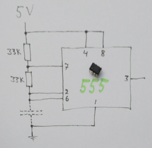
Well, remember that we'd like to get a new measurement every 20 ms. If we observe the output from the 555 oscillator and count the number of pulses that occur during a fixed period of time, that number will be proportional to the frequency. And it just so happens that the C64 is equipped with two 16-bit pulse counters (one per CIA chip). All we need to do is connect the 555 oscillator outputs to the CNT1 and CNT2 pins on the user port. These pins can act as asynchronous edge detectors, which means that pulses can be detected at any time relative to the C64 system clock. However, the counters can't keep up with frequencies higher than half the C64 clock frequency, or approximately 500 kHz. So we'll pick resistors for the 555 in such a way that the fastest signal—when the hand is far away from the antenna—is just below 500 kHz. I settled for 33 kΩ resistors.
At this frequency, during a 20 ms video frame, the counter will reach 10,000. But when the hand is near the antenna, the capacitance increases by 3%, the frequency decreases by 3%, and the counter only gets as far as 9700. And so we end up with a range of about 300 different values, just over 8 bits of precision. And because we're now using a sensible resistance (33 kΩ instead of 500 MΩ), and we're effectively averaging the output from several independent charge-discharge measurements, the analogue signal is of good quality to begin with.
Number crunching and envelope wrangling
All right, so we've got a pair of 16-bit readings, one for each antenna. How do we translate them into pitch and volume?
As discussed in the previous section, we won't be seeing numbers from the full 16-bit range, but rather a subrange of maybe 300 different values. The exact boundaries will depend on such factors as the size of each antenna and the size of the human performer. The first step of the computation will be to rescale the values from this subrange to the full 0–65535 range.
My software includes a calibration mode for this purpose. The performer initiates calibration by pressing a key on the keyboard (F1 or F3 depending on what antenna to calibrate) while holding the hand close to the antenna. The computer samples the value and considers this to be the lowest possible reading (highest capacitance). One second later, the computer samples the value and considers this the highest possible reading; within this time, the performer must have moved their hand far away from the antenna.
These readings are used to compute a scale factor and offset for transforming future readings into a number in the desired (full 16-bit) range. We also flip the range over, so the lowest number corresponds to the position farthest away from the antenna.
Now we have a value that's more or less proportional to the hand position, and thus to the desired pitch. But the SID chip wants a frequency, and frequency varies exponentially with pitch. Besides, our model of what's going on is somewhat simplified, and I'm not convinced that the measurement is perfectly linear to begin with. So the next step is to perform a non-linear transformation of this reading, to obtain the desired frequency value for the SID chip. This is done with an interpolated table lookup: The upper eight bits are used as an index into a precomputed table with 256 entries, and the lower eight bits determine how to mix two adjacent table entries to obtain a value in between. The values in the table increase monotonically (but not linearly) from the lowest to the highest desired frequency. The table was crafted through trial-and-error, and I ended up using a simple gamma correction curve (y = x^0.4 in the range 0–1).
Even if the performer's hand is quite still, the output from the pulse counter will be somewhat jittery. Therefore, the gamma-corrected value is low-pass filtered using a simple running average (the output from the filter is the average of the input and the previous output). This turns any rapid movements into smooth glides, for better or worse, but it also allows the performer to hold a precise pitch even when it falls somewhere between two integer values.
That concludes the frequency part, but what about the volume? Here, the SID chip presents us with a challenge: There is indeed a master volume parameter, but it's only a 4-bit register, which is somewhat crude. Furthermore, I wanted to use a breadbin case for this instrument for aesthetical reasons, but that meant I had to use the old model of the SID chip (6581), and unfortunately this model emits a distinct click every time you change the master volume setting.
What I ended up doing instead was to use the Voice 3 envelope readback register, $d41c, in a feedback loop. This register reports the current volume as an 8-bit quantity. Whenever the current volume is lower than the desired volume, I set the gate bit. When it is higher, I turn off the gate bit again. This update is performed twice per video frame, i.e. at 100 Hz. The attack and release parameters are set to $a and $8 respectively, for a reasonable compromise between a snappy response to hand movements and a clean sound (not audibly dithering between two volume levels).
Conclusion
Building a C64 Theremin was a fun project, but—somewhat unsurprisingly—the instrument is really hard to play. Still, it's a very special feeling to hold a tone in front of you in the air. Perhaps I'll sneak a brief Theremin part into some future musical performance video.
Posted Monday 29-Aug-2022 20:24
Discuss this page
Disclaimer: I am not responsible for what people (other than myself) write in the forums. Please report any abuse, such as insults, slander, spam and illegal material, and I will take appropriate actions. Don't feed the trolls.
Jag tar inget ansvar för det som skrivs i forumet, förutom mina egna inlägg. Vänligen rapportera alla inlägg som bryter mot reglerna, så ska jag se vad jag kan göra. Som regelbrott räknas till exempel förolämpningar, förtal, spam och olagligt material. Mata inte trålarna.
Tue 30-Aug-2022 01:00
Fri 2-Sep-2022 13:12
Thanks
Sat 3-Sep-2022 15:43
Sat 3-Sep-2022 17:58
Schematics & Code would be fantastic!
Maybe with a donate-link?
Thu 8-Sep-2022 22:47
Mon 14-Nov-2022 09:26
(Pieter Cuijpers)
Wed 14-Feb-2024 07:55