

Beagleboard VGA output

This article describes how you can extract a VGA signal from the LCD headers on a revision C beagleboard using two transistors and a bunch of resistors.
Overview
The beagleboard normally provides two video signals, DVI-D and S-Video. We're going to hook into some of the signals going from the OMAP chip to the TFP410 chip (DVI interface). This means that we'll tell the operating system to use the DVI-D interface (rather than S-Video), and read out the digital pixel values as they are transmitted. The DVI-D signal will not be affected, so you could connect both a VGA monitor and a DVI-D monitor and see the same image, as long as the video mode is compatible with both monitors.

Hardware
The hardware consists of three digital-to-analog converters (R-2R ladders), one each for the red, green and blue channel, and two level shifters for the sync signals.
The present solution assumes that the system is using 16-bit pixels in 5-6-5 format, but you can easily extend it to full 24-bit colour by making the resistor ladders longer.
You will need:
| Quantity | Part | Needed for |
|---|---|---|
| 13 | 60 Ω resistor | R-2R ladders |
| 19 | 120 Ω resistor | R-2R ladders |
| 2 | 100 Ω resistor | Level shifters |
| 2 | 1 kΩ resistor | Level shifters |
| 2 | NPN transistor, e.g. BC547C | Level shifters |
If you can't find resistors with these exact values, pick something close enough (but see "explanation" below). Try to match the ladder resistors so that one is exactly twice as resistive as the other. I ended up using 60.4 Ω and 121 Ω myself. Use low-tolerance metal film resistors for the ladders.
I would recommend some kind of header or other means of connecting and disconnecting the adapter from the beagleboard, in case you want to change things later. I settled for ribbon cables with headers on one end, soldered directly to the beagleboard at the other end. Another approach would be to solder two receptacles directly to the beagleboard, and plug two 20-way ribbon cables or a PCB with matching headers into them. It's up to you.
Schematic
Disclaimer: There could be errors in the diagram. Please double check all connections and pin numbers with the beagleboard system reference manual. If you've successfully built the adapter from the schematic, let me know and I'll remove this disclaimer.
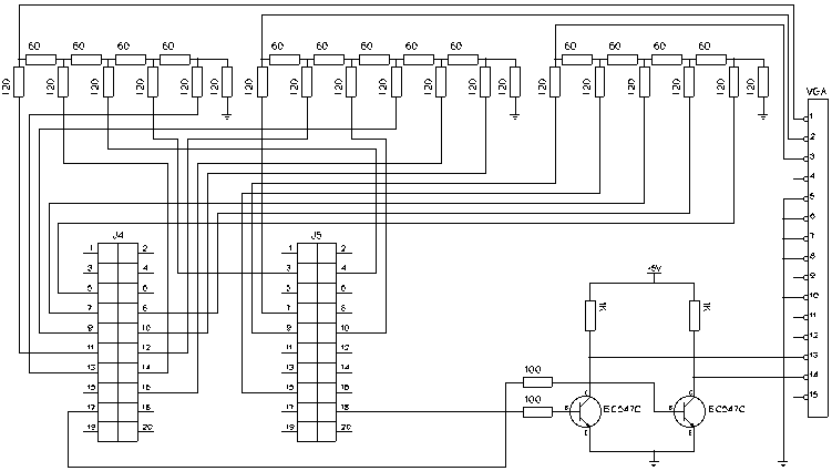
You can pick up the 5 V rail from J4:1 and ground from J4:20, or use the supply which is powering the beagleboard.
Explanation
The digital data lines carry the actual pixel values, expanded into 24 bits. The expansion is done by repeating the most significant bits, so e.g. the five red bits R4 R3 R2 R1 R0 are transmitted as R4 R3 R2 R1 R0 R4 R3 R2 on lines 23 through 16. A logic one is encoded as 1.8 V, and a logic zero is at ground potential. The resistor ladder has an equivalent series resistance of 60 Ω, and the VGA load (monitor) has an input impedance of 75 Ω according to the VGA specification. These resistances will form a voltage divider, converting the 1.8 V peak voltage into 1.8 * 75 / (75 + 60) = 1.0 V, which is the specified peak voltage for a VGA signal.
The sync signals are also at 1.8 V, but VGA requires 5 V TTL signals. The transistors act as TTL inverters. When the base is at ground potential, the transistor blocks, and the output signal is pulled up to 5 V via a 1 kΩ resistor. When the base is at 1.8 V, the transistor becomes open, essentially shorting the output signal to ground. Modern VGA monitors don't care about sync polarity. If you are planning to use a really old VGA monitor, you may have to add an extra inverter to either or both of the sync signals, depending on which video resolution you'll be using.
Caution
You probably already know this, but please take measures to avoid electrostatic discharge. If you're standing on a vinyl floor, wearing rubber shoes, combing your hair with a cat while handling the beagleboard, it may become damaged in non-obvious and strange ways.
Don't forget to verify that your newly attached wires aren't shorted, preferably before connecting power.
Software
Once the hardware is up and running, you may or may not get a picture on your VGA monitor. In either case, you should still get a valid DVI-D signal, allowing you to interact with the system. However, it's a good idea to issue the following commands over an ssh connection to the beagleboard, if possible, because you'll be manipulating the video timing parameters and the picture could disappear completely.
First, make sure to select your desired resolution at boot, e.g. omapfb.mode=dvi:1024x768-16@60. Avoid the R flag (reduced blanking).
When the system is up, cat the following file: /sys/devices/platform/omapdss/display0/timings
The output is in the format pixclock,xres/hfp/hbp/hsw,yres/vfp/vbp/vsw
| Field | Unit | Description |
|---|---|---|
| pixclock | picoseconds | The duration of one pixel |
| xres | pixels | Width of visible area (typically width of framebuffer) |
| hfp | pixels | Horizontal front porch |
| hbp | pixels | Horizontal back porch |
| hsw | pixels | Horizontal sync width |
| yres | rows | Height of visible area (typically height of framebuffer) |
| vfp | rows | Vertical front porch |
| vbp | rows | Vertical back porch |
| vsw | rows | Vertical sync "width" (in rows) |
Details are available in the kernel sources, in Documentation/arm/OMAP/DSS.
Getting an image at all
As root, experiment with the values in timings. If your monitor can display the current horizontal and vertical frequency, study how they change.
Try out various pixclock values first, until you have a stable image on the screen. Then tweak the porches and sync widths until you're satisfied with the size and placement of the image.
Fixing the right border
Some display lines may look strange. This is because the digital data bus we're sampling doesn't revert to black after each display line, so the rightmost pixel will "carry over" through the horizontal blanking period and into the beginning of the next line. Some monitors calibrate themselves during horizontal blanking, so whatever voltage they see during that time will be considered black in the upcoming line. Try to move the mouse cursor along the right end of the screen and see if you get this strange phenomenon.
If so, you can fix it easily by adding a black pixel to the right of each video line:
The timings file describes the dimensions of the actual video signal. The framebuffer, i.e. the chunk of memory where all the pixels are stored, is described using something called an overlay (/sys/devices/platform/omapdss/overlay0/...).
This means that we can modify the dimensions of the video signal, extending it somewhat to the right, without modifying the size of the framebuffer. The width has to be a multiple of eight pixels, so we have to go from e.g. 1024 to 1032.
This fixes the VGA signal, but unfortunately the DVI-D picture now has a small black border along the right edge. I don't know of a way to fix this properly, but most monitors allow the user to resize and move the image around freely, so you might be able to scroll those black pixels off the screen.
Examples
My monitor works with the following parameters:
| Boot mode | Modified timings |
|---|---|
| 1024x768-16@60 | 60000,1032/120/128/32,768/3/15/4 |
| 800x600-16@75 | 50000,808/34/198/20,600/23/37/6 |
I have configured my boot scripts to update the timings file automatically one second after x.org has started.
A better way?
Writing to timings directly is a kludge, and it's probably possible to get x.org to use VGA-compatible timings in the first place. This will definitely be an issue if you want to be able to switch between different video modes during regular use. I'm using a fixed resolution, so I haven't looked into this yet, but it's probably just a matter of putting the right thing in your xorg.conf.
Please post your suggestions on this page!
Troubleshooting
Verify that there are no shorts or breaks. When the device is on, verify that the board is configured for DVI-D output, and that the DVI-D signal is still working. Fill the screen with pixels in various colours (black, white, red, green, blue, ...) and study the DC voltage at various points in the circuit. Experiment with different resolutions and timings.
Posted Sunday 17-Jan-2010 17:00
Discuss this page
Disclaimer: I am not responsible for what people (other than myself) write in the forums. Please report any abuse, such as insults, slander, spam and illegal material, and I will take appropriate actions. Don't feed the trolls.
Jag tar inget ansvar för det som skrivs i forumet, förutom mina egna inlägg. Vänligen rapportera alla inlägg som bryter mot reglerna, så ska jag se vad jag kan göra. Som regelbrott räknas till exempel förolämpningar, förtal, spam och olagligt material. Mata inte trålarna.
Mon 18-Jan-2010 15:17
33 more comments hidden. Click to show all.
Paul
Mon 21-Oct-2013 08:45
Fri 31-Jan-2014 01:31
.....10k ohm... |/---- Red (repeat for Green and Blue)
hblank... -/\/\--|
...................... |\ 2n3904 transistor
........................ |
...................... gnd
Sat 29-Mar-2014 15:55
.....10k ohm... |/---- Red (repeat for Green and Blue)
hblank... -/\/\--|
...................... |\ 2n3904 transistor
........................ |
...................... gnd
Fri 30-Jun-2017 14:15
I have no experience with working with the confusing and complex LCD variations. to be honest, I don't know what to do with most the LCD pins on a BBB
for reference: https://www.element14.com/community/message/224509/l/bbb-and-tft-lcd-driver-board#224509